") Arduino旋轉(zhuǎn)編碼器的教程
Arduino旋轉(zhuǎn)編碼器的教程
步驟1:旋轉(zhuǎn)編碼器的脈沖流
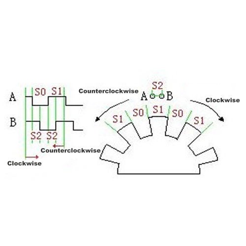
以下旋轉(zhuǎn)編碼器產(chǎn)生的脈沖流與上圖類(lèi)似。
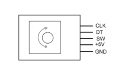
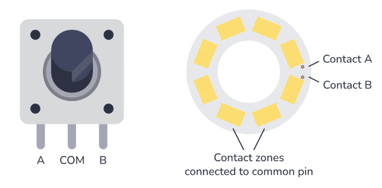
步驟2:旋轉(zhuǎn)編碼器的引腳排列
說(shuō)明:
GND-》 GND
+-》 + 5V
SW -》按下時(shí)旋轉(zhuǎn)編碼器的按鈕
DT-》數(shù)據(jù)
CLK-》數(shù)據(jù)2
DT之一或CLK引腳必須連接到Arduino Uno的中斷腳,或者DT和CLK都連接到中斷引腳。
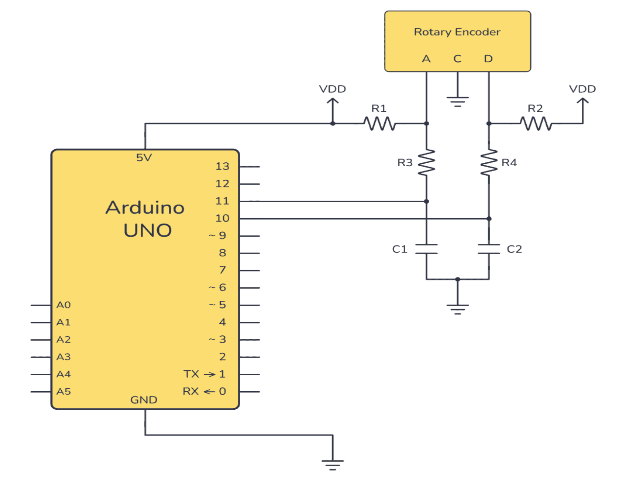
步驟3:示意圖
GNDàGND Arduino Uno
+à+ 5V Arduino Uno
SWàPIN 4 Arduino Uno
DT àPIN 3 Arduino Uno
CLKàPIN2 Arduino Uno
第4步:代碼
在以下教程中,PI將用作中斷Arduino Uno的N 2,而PIN 3僅用作常規(guī)輸入。
#define encoder0PinA 2
#define encoder0PinB 3
#define encoder0Btn 4
int encoder0Pos = 0;
void setup() {
Serial.begin(9600);
pinMode(encoder0PinA, INPUT_PULLUP);
pinMode(encoder0PinB, INPUT_PULLUP);
pinMode(encoder0Btn, INPUT_PULLUP);
attachInterrupt(0, doEncoder, CHANGE);
}
int valRotary,lastValRotary;
void loop() {
int btn = digitalRead(encoder0Btn);
Serial.print(btn);
Serial.print(“ ”);
Serial.print(valRotary);
if(valRotary》lastValRotary)
{
Serial.print(“ CW”);
}
if(valRotary {
Serial.print(“ CCW”);
}
lastValRotary = valRotary;
Serial.println(“ ”);
delay(250);
}
void doEncoder()
{
if (digitalRead(encoder0PinA) == digitalRead(encoder0PinB))
{
encoder0Pos++;
}
else
{
encoder0Pos--;
}
valRotary = encoder0Pos/2.5;
}
上面草圖的第10行用于啟用Arduino Uno的2號(hào)插針的中斷。在“ doEncoder”功能中,由旋轉(zhuǎn)編碼器計(jì)算得出。如果DT和CLK(Arduino Uno的引腳中斷)的值相同,則“ encoder0Pos”變量將增加/添加,除此條件外,“ encoder0Pos”變量將減少。
步驟5:說(shuō)明
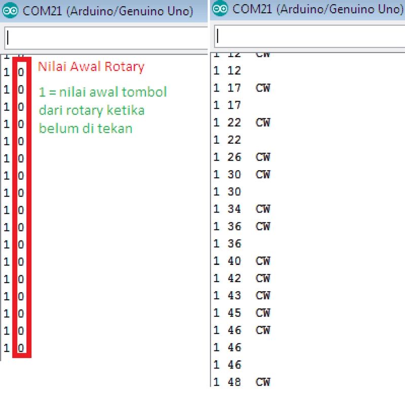
ValRotary值是已運(yùn)行的步驟數(shù)的值。 ValRotary值由旋轉(zhuǎn)傳感器編碼器讀數(shù)值除以2.5獲得。從測(cè)試中獲得的值為2.5,因?yàn)樾D(zhuǎn)編碼器的一個(gè)步驟可能會(huì)超過(guò)1,因此請(qǐng)根據(jù)每個(gè)步長(zhǎng)以及讀取延遲的增加將其值除以2.5。
第19-25行是確定旋轉(zhuǎn)旋轉(zhuǎn)編碼器是CW還是CCW的程序。第19-25行的解釋是當(dāng)前的旋轉(zhuǎn)編碼器讀數(shù)大于先前的旋轉(zhuǎn)數(shù)據(jù),然后表示為CW。
步驟6:輸出
責(zé)任編輯:wv
-
編碼器
+關(guān)注
關(guān)注
45文章
3667瀏覽量
135237 -
Arduino
+關(guān)注
關(guān)注
188文章
6477瀏覽量
187816
發(fā)布評(píng)論請(qǐng)先 登錄
相關(guān)推薦
用于 SPI 絕對(duì)編碼器的 Arduino 示例代碼
二進(jìn)制編碼器與絕對(duì)編碼器的區(qū)別
旋轉(zhuǎn)編碼器的類(lèi)型以及選擇與設(shè)計(jì)注意要點(diǎn)

旋轉(zhuǎn)編碼器可以收集并發(fā)出什么信號(hào),旋轉(zhuǎn)編碼器信號(hào)異常怎么處理

帶Arduino的旋轉(zhuǎn)編碼器設(shè)計(jì) 旋轉(zhuǎn)編碼器的工作原理和特點(diǎn)
旋轉(zhuǎn)編碼器在PLC中怎么編程
旋轉(zhuǎn)式編碼器的工作原理和特點(diǎn)
旋轉(zhuǎn)編碼器在數(shù)控機(jī)床中的應(yīng)用
旋轉(zhuǎn)編碼器的常見(jiàn)類(lèi)型
旋轉(zhuǎn)編碼器的種類(lèi)和接線方法
編碼器分辨率是什么意思 編碼器分辨率和脈沖數(shù)的關(guān)系
如何將增量旋轉(zhuǎn)編碼器與Arduino連接
旋轉(zhuǎn)編碼器的工作原理,旋轉(zhuǎn)編碼器的作用功能及應(yīng)用


 工商網(wǎng)監(jiān)
評(píng)論