 電子發燒友App


Abstract: This circuit provides flexible fault protection for a 4-20mA current loop. In addition, it includes circuitry for recovering digital signals (such as the HART protocol) imposed on the loop.
4-20mA current loops consist of a power source and current-measuring device at the control end, and a field transmitter that senses process-variable information (like temperature or pressure) and converts it to a current (Figure 1). Most 4-20mA industrial loops are powered by 24VDC, but that voltage can range from 12V to 36V. The loop voltage in older systems can be even higher.

Figure 1. Basic architecture of a 4-20mA current loop.
Many such applications require current limiting or fault protection or both. For example, a short circuit or other high-current fault in one of several loops powered by a single source can produce a power-supply failure that disables all transmitters powered by that source. Intrinsically safe loops, on the other hand, include a barrier module that limits current and voltage to the transmitter. Fault-protected sources can add another level of system safety. Setting a current limit on each loop lets you size the power supply accurately without over-specifying it.
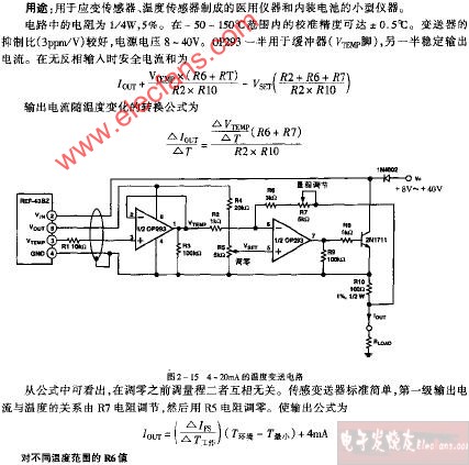
Figure 2 shows one form of flexible fault protection for the 24VDC power supply of a 4-20mA loop. Also included is circuitry for recovering a digital signal superimposed on that loop. U1 (a high-side current-sense amplifier with comparator and reference) senses the loop current in R1 as an 8-40mV voltage and amplifies it by 100, producing an output-voltage range of 0.8V to 4V. That output (VOUT) can directly drive external meters, strip-chart recorders, and A/D converter inputs.

Figure 2. This circuit provides fault protection and digital-signal recovery for a 4-20mA current loop.
The selected fault-current trip point (for U1's internal comparator #1) is set by the R2-R3 voltage divider at 0.6V. Setting the trip point for a 50mA fault, for instance, establishes the following relationship between R1 and R2:
R2/(R1 + R2) = 0.6V/(R1*100*IFAULT) ==> R1 = 15.67*R2.
When faults occur, the COUT1 output assumes a high impedance and is pulled high by R10. The noninverting cascaded-transistor pair Q2-Q3 provides an interface to the high loop voltage while preserving a proper logic polarity for controlling the gate of Q1. Q1 is held in the OFF state until U1's comparator #1 is reset by the pushbutton PB1 or other reset signal. (To disable this comparator's latched output, tie the RESET# pin to ground.) Zener diode ZD1 protects Q1's gate-source junction from overvoltage.
U2 and associated circuitry can recover any digital information imposed on the 4-20mA loop current by modulation. The HART protocol, for instance, typically uses frequency-shift keying (FSK) between 1200Hz and 2400Hz to modulate the loop current between ±0.5mA levels. (For this circuit, the modulated signal at VOUT (pin 2 of U1) is ±0.1V.) VOUT from U1 is capacitively coupled to U2 and amplified by that device to recover such digital signals.
U1 includes a second comparator with inverting input, which can be used to cancel the inversion in U2's digital-signal output. Though not essential, this comparator output (COUT2) can also (as shown) present the recovered digital signal as a clean rectangular waveform for driving external circuitry.
4-20mA current loops consist of a power source and current-measuring device at the control end, and a field transmitter that senses process-variable information (like temperature or pressure) and converts it to a current (Figure 1). Most 4-20mA industrial loops are powered by 24VDC, but that voltage can range from 12V to 36V. The loop voltage in older systems can be even higher.
Figure 1. Basic architecture of a 4-20mA current loop.
Many such applications require current limiting or fault protection or both. For example, a short circuit or other high-current fault in one of several loops powered by a single source can produce a power-supply failure that disables all transmitters powered by that source. Intrinsically safe loops, on the other hand, include a barrier module that limits current and voltage to the transmitter. Fault-protected sources can add another level of system safety. Setting a current limit on each loop lets you size the power supply accurately without over-specifying it.
Figure 2 shows one form of flexible fault protection for the 24VDC power supply of a 4-20mA loop. Also included is circuitry for recovering a digital signal superimposed on that loop. U1 (a high-side current-sense amplifier with comparator and reference) senses the loop current in R1 as an 8-40mV voltage and amplifies it by 100, producing an output-voltage range of 0.8V to 4V. That output (VOUT) can directly drive external meters, strip-chart recorders, and A/D converter inputs.
Figure 2. This circuit provides fault protection and digital-signal recovery for a 4-20mA current loop.
The selected fault-current trip point (for U1's internal comparator #1) is set by the R2-R3 voltage divider at 0.6V. Setting the trip point for a 50mA fault, for instance, establishes the following relationship between R1 and R2:
R2/(R1 + R2) = 0.6V/(R1*100*IFAULT) ==> R1 = 15.67*R2.
When faults occur, the COUT1 output assumes a high impedance and is pulled high by R10. The noninverting cascaded-transistor pair Q2-Q3 provides an interface to the high loop voltage while preserving a proper logic polarity for controlling the gate of Q1. Q1 is held in the OFF state until U1's comparator #1 is reset by the pushbutton PB1 or other reset signal. (To disable this comparator's latched output, tie the RESET# pin to ground.) Zener diode ZD1 protects Q1's gate-source junction from overvoltage.
U2 and associated circuitry can recover any digital information imposed on the 4-20mA loop current by modulation. The HART protocol, for instance, typically uses frequency-shift keying (FSK) between 1200Hz and 2400Hz to modulate the loop current between ±0.5mA levels. (For this circuit, the modulated signal at VOUT (pin 2 of U1) is ±0.1V.) VOUT from U1 is capacitively coupled to U2 and amplified by that device to recover such digital signals.
U1 includes a second comparator with inverting input, which can be used to cancel the inversion in U2's digital-signal output. Though not essential, this comparator output (COUT2) can also (as shown) present the recovered digital signal as a clean rectangular waveform for driving external circuitry.


 工商網監
工商網監
評論